Valve Procurement: Nominal Diameter vs. Actual Interface Dimensions
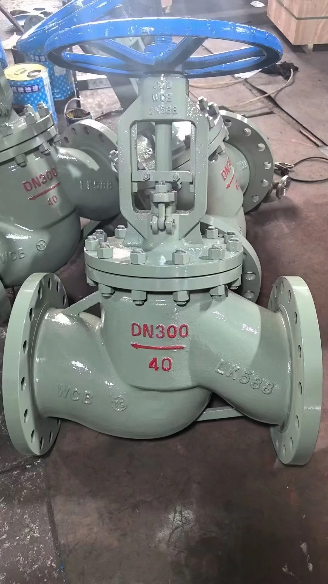
What Is Nominal Diameter (DN)? Why It Does Not Equal Actual Measured Value
When procuring industrial piping valves, many newcomers often mistakenly assume that the nominal diameter (Nominal Diameter, abbreviated as DN or NPS) is the actual inner or outer diameter of the valve interface. In reality, the nominal diameter is a designation or nominal size that facilitates the standardized design of piping systems. For instance, a DN50 valve does not mean that the physical outer or inner diameter of its connection port is precisely 50 millimeters. Different piping standards (such as national standard GB, American standard ANSI, German standard DIN, Japanese standard JIS, etc.) have clear and different provisions for the pipe outer diameter corresponding to the same DN designation. Therefore, procuring based solely on nominal diameter can easily lead to interface mismatch issues during on-site installation, such as mismatched flange bolt hole spacing or threads that cannot be screwed in.
Analysis of Actual Interface Dimensions Under Different Connection Methods
To ensure that the procured valves can be seamlessly installed into existing pipelines, procurement personnel need to master the actual interface parameters of various connection methods. For flanged connections, the key factors determining installation are the flange outer diameter, bolt hole circle diameter, number of bolt holes, and bolt hole diameter, all of which are closely related to the nominal pressure class; for threaded connections, it is necessary to distinguish thread profile standards such as NPT, BSPT, and G threads, as well as sealing methods; for welded connections, it is necessary to verify the specific outer diameter and wall thickness of the pipe to facilitate groove butt-welding joint processing. Understanding these details not only ensures the tightness of pipeline connections, but also avoids construction delays caused by on-site grinding or re-machining.
Impact of Full Port and Reduced Port Valves on Flow Control
In addition to the external connection interfaces, the actual internal flow passage diameter of the valve is also a key point in model selection. Taking common ball valves as an example, the market offers a distinction between full port (Full Port) and reduced port (Reduced Port). The inner diameter of the internal flow passage of a full port valve is basically consistent with the inner diameter of the pipe, offering minimal medium flow resistance, making it suitable for operating conditions sensitive to pressure loss or requiring pigging; whereas the seat bore of a reduced port valve is smaller than its nominal diameter, which, despite reducing manufacturing cost and valve volume, introduces a certain degree of resistance and pressure drop to system flow control. If flow passage diameter requirements are ignored during procurement, it may result in system flow rates failing to reach design targets.
Valve Procurement Inquiry Preparation and Technical Verification Checklist
To improve communication efficiency and ensure accurate model selection, before issuing an inquiry to a supplier or confirming an order, it is recommended to verify and provide specific technical parameters according to the following checklist: – Clearly state the nominal diameter (DN/NPS) and design nominal pressure (PN/Class) of the piping system. – Provide the actual connection dimensions of the pipe, including the outer diameter and wall thickness of welded pipes, or the standard designation and pressure rating of flanges. – Confirm the required connection type (flanged, female threaded, male threaded, butt welded, socket welded, or ferrule fitting, etc.). – Specify the medium type, operating temperature, and flow requirements, making clear whether a full port design is required. – If it is a special operating condition, provide on-site space limitation drawings and confirm the face-to-face (Face-to-Face) dimensions of the valve with the supplier.
Interface Verification Recommendations in Piping Maintenance and Field Replacement
When replacing an old valve, the interface should be verified by combining nameplates, applicable standards, engineering drawings, and actual measurements, rather than relying solely on a single piece of information. When measurement or disassembly involves equipment maintenance, qualified personnel should complete shutdown, isolation, pressure relief, and safety verification in accordance with on-site safety procedures; disassembly under pressure is not permitted. For non-standard modifications or pipelines mixing different standards, verified interface data and drawings should be provided to the supplier to confirm whether the flange, threads, sealing surfaces, and face-to-face length match before placing an order.
Prepare an enquiry